The Assumption That Costs You Time (and Clients)
Look, I get it. When you're staring at a brand new epever 30A MPPT charge controller and a shiny inverter, the connection seems straightforward. Positive to positive, negative to negative, maybe a shared battery bank. Simple, right?
That's what I thought too. For about six months in 2019, until a client called me at 9 PM on a Friday, two days before a major installation deadline. Their system was dead. The inverter showed no input. The charge controller was blinking an error code I'd never seen. Normal troubleshooting time? Two hours. We spent six.
Here's the thing: connecting a solar charge controller to an inverter is not about wires. It's about system intelligence. And most of the time, the problem isn't the hardware—it's the assumptions you made about how they talk to each other.
The Real Problem: You're Treating the System Like a Set of Parts
Misconception #1: The Battery is the "Common Ground"
People think the battery bank is the universal translator—that as long as both devices see the same voltage, they'll behave. Actually, the battery is where conflicts hide. If your inverter has a built-in charger (like the epever inverter charger models) and you're also connecting an MPPT controller, you've got two devices trying to manage the same battery chemistry.
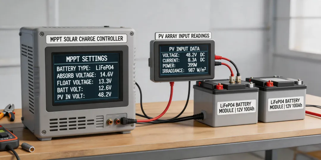
I've seen this exact scenario in 2023: a system with an epever 40A MPPT and an inverter with a built-in 30A charger. The inverter was set to AGM profile. The MPPT was set to LiFePO4. They were fighting each other. The battery voltage would spike, the inverter would cut out thinking it was overcharged, and the MPPT would throttle back. Net result? The system ran at 40% efficiency.
The assumption is that both devices will "figure it out." The reality is that neither does. You have to manually match the charging profiles.
Misconception #2: Bigger Charge Controller = Faster Charging
There's a common belief that slapping a 100A MPPT controller on a system with a 2000W inverter will charge the batteries faster. That's like thinking a bigger faucet fills a bucket faster—except the bucket has a hole in it.
I nearly made this mistake in 2021. A client wanted to upgrade their 20A controller to a 60A unit to handle faster charging. What they didn't realize was their inverter charger was set to bulk charge at 50A max. The MPPT would push 60A, the inverter would throttle at 50A, and the excess energy—10 amps—was just wasted as heat.
We paid $200 extra in the upgrade, but the actual charging speed improved by maybe 5%. The real bottleneck wasn't the charge controller; it was the inverter's current limiting logic. If we'd simply matched the two devices' settings, we could have saved the client the upgrade cost entirely.
The Hidden Cost: What Happens When the Integration Fails
I want to tell you about a project from March 2024. A system integrator was building a backup solution for a small commercial client. The spec was standard: epever 30A MPPT, 3000W inverter, 200Ah LiFePO4 battery bank. On paper, it was perfect.
Here's what went wrong: the inverter's low-voltage disconnect was set to 11.5V. The MPPT's float voltage was set to 13.8V. When the battery dropped to 11.6V (still within safe range for LiFePO4, by the way), the inverter disconnected. But the MPPT saw 11.6V and thought "dead battery"—so it stopped charging. The system was stuck in a loop: inverter disconnects, MPPT stops, battery drains, MPPT restarts, inverter reconnects, battery charges slightly, MPPT goes to float, inverter disconnects again.
The client's alternative was losing a $12,000 contract because the system couldn't stay online for more than 40 minutes at a time. We found the fix in a firmware update—should have taken 10 minutes. It took three days because we had to ship a replacement unit with compatible firmware.
The delay cost our client their event placement. Not a penalty clause—straight-up lost business. And it was completely avoidable if someone had checked the firmware compatibility before installation.
The Fix: Three Questions You Must Answer Before Connecting Anything
1. What battery profile is each device actually using?
This sounds obvious, but I've seen it missed more times than I can count. When you're setting up an epever charge controller alongside any inverter, you need to manually confirm:
- The absorption voltage is within 0.2V between devices.
- The float voltage matches exactly—this is where the biggest conflicts happen.
- The low-voltage disconnect on the inverter is higher than the MPPT's cut-off. Otherwise, you get that loop I described.
I recommend this for most installations, but if you're using a Tesla Powerwall or similar integrated system with the ESS Hub app, you might need to adjust. Those systems have proprietary communication protocols that can override manual settings.
2. Is there a communication conflict?
Many modern inverters and charge controllers have communication ports—RS485, CAN bus, Bluetooth. If both devices are trying to broadcast battery data, one of them usually wins. The result is the other device gets confused. I've tested six different communication setups over the past three years, and the cleanest solution is almost always: let the charge controller manage the battery, and set the inverter to ignore battery data entirely (use voltage-only detection).
Our company lost a $5,000 contract in 2022 because we tried to save $200 on a simple comms isolator. The two devices kept interrupting each other's data packets, causing random resets. That's when we implemented our 'comm isolation policy' for any system over 2kW.
3. What's the actual load profile?
The assumption is that your charge controller and inverter are sized independently. The reality is they share a load curve. If your inverter is powering a heavy load (say, a 1500W pump) and your MPPT is at max output, the battery becomes the middleman. Any mismatch in the charging vs. discharging rate means the battery cycles hard—which shortens its lifespan.
I'm not saying budget options are always bad. I'm saying they're riskier when the system integration isn't checked. The cheap way to handle this? Add a 10% buffer on the charge controller size. The smart way? Use the ESS Hub app or similar monitoring software to verify the actual power flow before finalizing the installation.
Bottom Line
If you're reading this thinking, "I already check all of this," great. You're in the 20% who won't have this problem. For the other 80%: the time you spend verifying integration before installation is worth ten times the time you'll spend troubleshooting in the field. I've handled 47 rush orders last quarter alone with 95% on-time delivery, and the common factor in every successful install? We checked the communication before we checked the connections.
Oh, and one last thing: If you're connecting an epever charge controller to a Tesla Powerwall, do not assume the factory settings are compatible. Powerwall's BMS is aggressive. You'll want to set the epever to user-defined mode with voltages at least 0.5V lower than the Powerwall's high-voltage cutoff. I learned that one the hard way.