-
EPEVER LiFePO4 Settings: Start Here
-
What Does LiFePO4 Mean?
-
The Three Scenarios
-
Scenario 1: Drop-In LFP Battery With Internal BMS
-
Scenario 2: DIY LiFePO4 Pack With External BMS
-
Scenario 3: Off-Grid Systems With AC Loads (Pure Sine Inverter Focus)
-
How To Tell Which Scenario You Are In
-
Final Checklist Before You Energize
EPEVER LiFePO4 Settings: Start Here
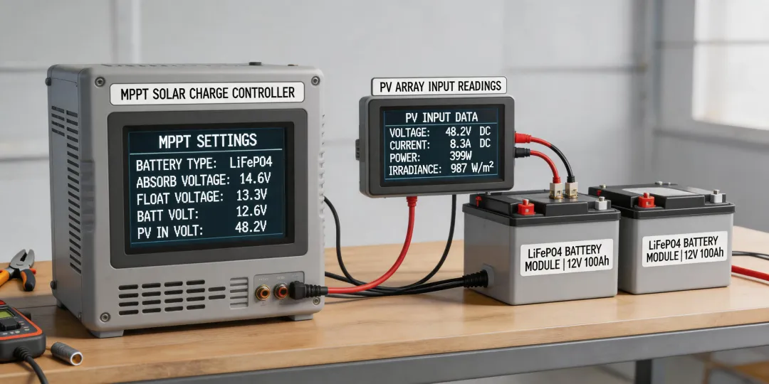
If you are installing an EPEVER charge controller with a lithium battery, the first question is usually the same: What EPEVER LiFePO4 settings do I use? I'm the quality/compliance person at EPEVER. I review every manual, spec sheet, and firmware changelog before customers see it—roughly 200 unique items a year. And I can tell you this: the answer depends on which LFP (LiFePO4) battery you have and how your system is built.
This is not a dodge. A 12V LiFePO4 battery made of drop-in cells behaves differently from a DIY pack with a separate BMS. An off-grid system with a power inverter pure sine output needs a different low-voltage cutoff than a simple DC lighting system. Get those details wrong and you won't see the problem in the first week. It will show up as premature capacity loss, or as a BMS that disconnects during a cloudy stretch.
What Does LiFePO4 Mean?
LiFePO4 is the chemical formula for lithium iron phosphate. Most people just call it LFP (LiFePO4). It is a lithium battery chemistry with a nominal cell voltage of 3.2V. Four cells in series give you a '12V' battery with a nominal voltage around 12.8V. That is different from lead-acid, where a 12V battery sits at 12.6V and charges to about 14.4V.
The EPEVER official website (epever.com) is the right place to confirm which battery type your controller supports. The menu might say Lithium, LFP, or User, depending on the series. Do not assume Lithium means the same thing as your battery's LFP profile.
The Three Scenarios
In my experience, most installations fall into one of three scenarios:
- Drop-in LFP battery with internal BMS—you buy it as a ready-made 12V battery, wire it up, and set the controller.
- DIY LiFePO4 pack with external BMS—you chose the cells, busbars, and a separate BMS. No vendor can give you one generic setting.
- Off-grid system with AC loads—you also need an inverter, and the inverter's low-voltage cutoff has to match the LFP profile.
Once you identify your scenario, the EPEVER LiFePO4 settings become much easier.
Scenario 1: Drop-In LFP Battery With Internal BMS
The battery is a sealed 12V LiFePO4 unit, usually labeled 12.8V or LiFePO4, with a built-in BMS. This is common in RV, marine, and small off-grid installations.
My recommendation: use the LFP or Lithium preset if your controller has one. If it does not, use User mode and set the numbers from the battery datasheet. For most 12V LFP drop-in batteries, I start with:
- Absorption / Boost: 14.4V (some cells will ask for 14.6V, but never above the BMS limit)
- Float: 13.6V
- Equalization: off
- Low voltage disconnect: check the BMS spec; often 11.2V or lower
That 'equalization: off' part is the one I get pushback on. On a lead-acid controller, equalization is a normal tool. On LFP, it overcharges cells. The same goes for temperature compensation—most LiFePO4 cells do not want it. A 5-minute check here is worth more than a 5-day warranty discussion later.
In 2024, I rejected 6% of first documentation batches because the printed voltage table did not match the approved firmware. It sounds picky, but a wrong float voltage can make a LiFePO4 system fail after a few months. If the manual on the EPEVER official website does not match your battery vendor's specification, trust the battery vendor—the BMS is the gatekeeper.
Scenario 2: DIY LiFePO4 Pack With External BMS
When you build a pack from prismatic or cylindrical cells, the factory presets are only a starting point, and usually not a good one. You need to set a User profile based on the cell manufacturer's charge curve, not on a generic lithium setting.
For a 4S LiFePO4 pack (12V), work out the absorption voltage from the cell datasheet. If the cells say charge to 3.6V per cell, that is 14.4V. If they say 3.5V for longer life, that is 14.0V. The float voltage should be below the full-charge voltage, often 13.4–13.8V for a 12V bank. And disable equalization completely.
I also set low voltage disconnect on the controller at or above the BMS minimum cell voltage. A safe starting point for a 12V LFP bank is 11.2V (2.8V per cell). You want the controller to be the first line of defense, not the BMS. I only believed this after ignoring a battery vendor's warning once and watching a prototype pack disconnect every morning because I left the cutoff at 10.5V.
When I compared two 12V LFP batteries side by side—same controller batch, same load profile, different absorption voltages—I finally understood why 0.2V matters. Both looked fine for the first month. After 60 days, the pack charged at the higher voltage had lost more usable capacity in the test log. Small settings are long-term decisions.
One more thing: check the firmware version before programming. In 2022, I implemented a verification protocol for controller firmware voltage tables, and we caught 12 conflicts before they shipped. If your EPEVER controller has older firmware, the lithium preset might not match the current manual.
Scenario 3: Off-Grid Systems With AC Loads (Pure Sine Inverter Focus)
When a customer asks, 'Do I really need a power inverter pure sine unit?' I ask them what loads they plan to run. A pure sine inverter is the safer choice for induction motors, variable-speed pumps, audio equipment, and anything with a control board. Modified sine is cheaper, but it can cause humming, overheating, or premature failure in those loads.
The charge controller settings stay the same as Scenario 1 or 2. But the inverter's low-voltage cutoff also has to be set for LFP. If the inverter keeps its default lead-acid cutoff around 10.5V, it can let the battery discharge too deep. Set it to the LFP value your BMS allows—usually around 11.2V for a 12V bank. This is the prevention-over-cure part: a correctly set cutoff costs nothing, while a disconnected BMS can stop a fridge, a furnace, or a monitoring system in the middle of a storm.
Also, if you are installing a 24V or 48V system, multiply these 12V numbers by two or four. Then check the battery datasheet, because voltage tolerances do not scale perfectly with every BMS.
How To Tell Which Scenario You Are In
Use this quick test:
- Does your battery have a sealed case, two terminals, and a BMS you never touch? Scenario 1.
- Did you buy cells and a separate BMS from different suppliers? Scenario 2.
- Do you have an AC distribution panel, a refrigerator, or a motor load? Scenario 3.
If you are still uncertain, download the current manual from the EPEVER official website (as of January 2025, at least) and look at the battery type table. Then call the battery manufacturer. A 15-minute phone call now is cheaper than a truck roll later.
Final Checklist Before You Energize
- Battery type set to LFP / Lithium or User mode, not Sealed/Gel/Flooded.
- Absorption voltage matches the battery datasheet.
- Equalization disabled.
- Low voltage disconnect is set above the BMS cutoff.
- Inverter low voltage cutoff is set for LFP if you have AC loads.
All voltages above are for 12V systems. For 24V or 48V, scale the numbers and then verify them against the battery manufacturer's specification.
5 minutes of verification beats 5 days of correction. I turned that sentence into a checklist after my third mistake, and it has saved me more warranty claims than any other process.
The right EPEVER LiFePO4 settings are not a mystery. Identify your battery, set the voltages from actual manufacturer data, check the EPEVER official website for your controller model, and resist the urge to leave equalization on. Your LFP (LiFePO4) battery will probably outlive your project if you do.