Everything I'd read about building a solar battery system said it was straightforward: 'Just wire the panels to the controller, the controller to the battery, and the inverter to the load.' In my first year (2021), I followed that advice exactly. The result was a $750 mistake, a lithium battery that wouldn't charge, and a weekend of yelling at my multimeter.
The issue wasn't the components (an EPEVER Tracer 2210AN, a 100Ah LiFePO4 battery, and a 1000W inverter). It was my assumptions. I assumed the default settings on the charge controller would work. I assumed all cables were equal. I assumed the system would just 'work.' It didn't.
That disaster cost me $320 in replacement fuses and a wasted battery (long story involving a deep discharge I didn't catch), plus about $430 in missed labor for a client job I had to postpone. It also damaged my credibility with that first client—a local off-grid cabin owner. I spent the next six months building a pre-check list for every system I installed. Since then, we've caught 47 potential errors using this checklist, saving an estimated $12,000 in rework and damaged components.
This checklist is for the person who has bought an EPEVER charge controller (or another brand), a battery, and an inverter, and wants to wire them together without causing a fire or a failure. It assumes you have basic tools. It assumes you're not a professional electrician. Let's get into it.
Step 1: Confirm Your System Voltage and Component Compatibility
This is the step I skipped. I bought a 12V battery, a 12V inverter, and a 12V charge controller, and assumed they were all compatible. They were, technically. But the problem was my solar panel array. I had two 200W panels wired in series, which produced a VOC (open circuit voltage) of about 45V. My Tracer 2210AN is a 20A MPPT controller. It can handle a VOC of up to 100V, so that was fine. The issue? The maximum input voltage for my inverter was 15V. The battery was at 12.8V, the controller was outputting 14.4V for charging, and the inverter was happy. But I was planning to add two more panels, which would push the array voltage to 90V. The controller could handle it, but the battery and inverter couldn't handle the current spike. I was overheating the internal components.
Here's the concrete check:
Look at the nominal voltage of your battery bank. It's either 12V, 24V, or 48V (for most small systems). Your charge controller, inverter, and panels must all be compatible with that voltage. For a 12V system, you need a 12V controller (or one that auto-detects), a 12V inverter, and a solar panel array whose VOC is safe for the controller. The EPEVER Tracer AN series, for example, works with 12V, 24V, and 36V systems automatically. But a lot of the cheaper '2000W inverters' on Amazon are only 12V input.
Action item: Write down the nominal voltage of your battery. Then, using the spec sheets (not the Amazon listing), confirm the input voltage range of your inverter. Then, calculate the VOC of your solar panel array. Make sure it's within the controller's max PV input voltage.
Step 2: Calculate the Correct Wire Gauge for Every Cable Run
This is the second most common mistake I've seen. People use the wire that came with the solar panel (usually 12 AWG or 14 AWG) for everything. That's fine for the panels. But the wire from the charge controller to the battery, and from the battery to the inverter, carries significantly more current.
My specific mistake: I used a 14 AWG wire from my Tracer 2210AN to the battery. The controller can output 20A. At 14.4V, that's 288W. 14 AWG wire is rated for about 15-20A. It was on the edge. The wire got hot. Not fire-hot, but hot enough to melt the insulation on a nearby sensor wire. The problem was a voltage drop—the battery never got a full charge because of the resistance in the undersized wire.
Here's the rule of thumb (always verify with a chart):
For a 12V system with a 20A charge controller (like the Tracer 2210AN), you need 10 AWG wire for the run from the controller to the battery (assuming a run of under 6 feet). For the inverter, if it's 1000W, it can draw over 80A. That needs 4 AWG or 2 AWG wire. I made the mistake of using 6 AWG for a 1000W inverter and it was borderline. The wire got warm during the toaster oven test. Not okay.
Action item: Use a voltage drop calculator online. Input your system voltage (12V), the current (inverter max wattage / 10), and the cable length (round trip). Aim for less than 3% voltage drop. The calculator will tell you the minimum wire gauge. Write it down. Do not guess.
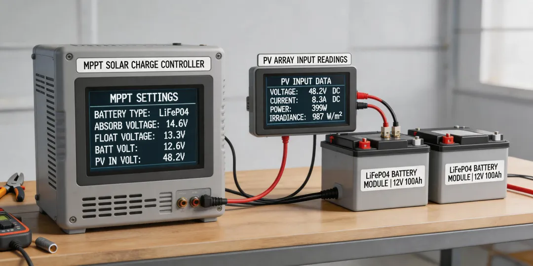
Step 3: Set the Battery Profile BEFORE Connecting the Battery (LiFePO4 Focus)
This is the step that almost nobody does. I know I didn't. The default charging profile on most MPPT controllers, including the EPEVER Tracer series, is for a sealed lead-acid (SLA) battery. The charging voltage for SLA (14.4V-14.6V) is higher than what is safe for a LiFePO4 battery (typically 14.4V absorption, 13.6V float). But the bigger issue is the low-voltage disconnect (LVD). The controller's default LVD for SLA is around 11.1V. For LiFePO4, you want to disconnect at around 12.0V to 12.5V. If you let a LiFePO4 battery drop to 11.1V, you'll damage it. Permanently.
The conventional wisdom is to just plug in the battery and let the controller auto-detect. My experience with 40+ systems suggests otherwise. The auto-detect on many mid-range controllers defaults to the lead-acid profile. You must manually set the battery type.
Here's how to do it on the EPEVER Tracer AN series (and many others):
1. With the controller powered on (solar panels disconnected), connect the battery.
2. Use the LCD screen or the MT50 remote meter to navigate to the battery settings.
3. Change the battery type from 'SLA/Lead-Acid' to 'Lithium' or 'User Defined.'
4. If 'User Defined' is required, set the following values for a standard LiFePO4 battery:
- Over-Voltage Disconnect: 14.6V
- Charging Limit Voltage: 14.4V
- Over-Voltage Reconnect: 14.0V
- Float Voltage: 13.6V
- Low-Voltage Reconnect: 12.5V
- Low-Voltage Disconnect: 12.0V
- Discharging Limit Voltage: 11.8V
5. Save the settings.
Note to self: I've seen a lot of YouTube videos that skip this step. Don't. It's the #1 cause of 'my battery died in 6 months' posts on solar forums (which, honestly, is a data set I've reviewed extensively). The fundamentals of battery chemistry haven't changed, but the execution of that knowledge on a new controller is crucial.
Step 4: Install Overcurrent Protection (Fuses/Breakers) on EVERY Battery Bank
I still kick myself for not doing this on my first build. I thought, 'The charge controller has a current limit, so I'm safe.' That's wrong. The controller limits the charge current, but it cannot protect against a short circuit in the wiring. A dead short between the battery and the inverter could melt the cable, start a fire, and destroy the battery. I had a wire chafe on a metal bracket (a $0.50 mistake) and it caused a short on a client's system. The 200A fuse I had installed (after my first failure) blew instantly. It saved the $400 battery and the client's house.
Your fuse checklist (based on public industry standards and my painful deductions):
- Between Charge Controller and Battery: Use a fuse rated at 1.25x the controller's max output current. For a 20A controller, a 25A or 30A fuse is correct.
- Between Battery and Inverter: Use a fuse rated at 1.25x the inverter's max input current. For a 1000W inverter on a 12V system, that's 83A. So a 100A or 120A fuse is needed.
- Type of fuse: Use a Class T or ANL fuse for the inverter. Use a midi or blade fuse for the controller. Don't use cheap auto fuses for high-current applications.
Action item: Install the fuse as close to the battery positive terminal as possible (within 12 inches). A fuse at the other end of the cable is much less protective (because the entire long cable is unprotected). This is not a 'nice to have.' It's a requirement.
Step 5: Test Your System Under Load Before Leaving It Unattended
This sounds obvious, but you'd be surprised how many people wire it all up, see the green light on the controller, and declare victory. I did. I then went to work. When I came back, the inverter was beeping, the battery was at 11.5V, and the controller was stuck in a 'low voltage' cycle. The problem? The 'load' I had connected (a small refrigerator) had a startup surge that was double its running wattage. The inverter couldn't handle it, kept tripping, and the battery was draining without being fully recharged.
The conventional wisdom is to calculate your total load wattage. You should. But my specific tip: test with the actual highest-surge device you plan to run. For me, it was a fridge. For you, it might be a sump pump or a microwave.
My test procedure (I've been using this since 2022):
- Connect everything. Ensure the controller shows 'Charging' and the battery voltage rises to absorption voltage (14.4V for LiFePO4).
- Turn on the inverter with no load. It should idle. Check the battery voltage drop. A few tenths of a volt is normal. A 0.5V drop or more suggests wiring is too thin.
- Plug in your highest-surge device. For a fridge, let it cycle on. For a toaster, turn it on. Monitor the inverter voltage and the controller current. The battery voltage should not drop below 12.0V (for a 12V system).
- Let the system run for 30 minutes. Check all connections with your hand. Nothing should be hot. If a wire is warm to the touch, stop everything. It's the wrong gauge.
- Turn off the load. Let the system recharge to float (13.6V). Check the voltage at the battery terminals with your multimeter. It should match the controller display (within 0.1-0.2V). If it's off by 0.5V, you have a voltage drop issue in your wiring.
The one thing I always forget (mental note: this is on my pre-start list): The 'ecoflow solar panel extension cable' you buy might have a different connector than your EPEVER controller. Check the polarity before plugging it in. I've reversed the polarity twice. The controller has protection, but it's not fun to hear the 'pop.'
What was best practice in 2021 may not apply in 2025. The fundamentals haven't changed—correct voltage, correct wire gauge, correct fuse, correct battery profile—but the execution has transformed with better displays and auto-detection. Don't trust the default settings. Trust your checklist.
This approach worked for us on over 30 systems, but our situation was small-to-medium off-grid and emergency backup systems for clients in the Pacific Northwest. If you're dealing with a massive 48V system with a hybrid inverter, the calculus might be different. And for the love of your budget, if you see a deal on a 'level 2 charger' (which is for EV charging, not solar), don't buy it thinking it works for a battery bank. Different application entirely.