-
Step 1: Verify the LiFePO4 Voltage Curve (Don't Trust the Default)
-
Step 2: Calculate Your Array Voltage vs. Controller Limit
-
Step 3: Don't Forget the Battery Communication (If Applicable)
-
Step 4: Grounding and Fusing (The Overlooked Safety Check)
-
Step 5: Test the System Under Load (Not Just at Idle)
-
Final Thought: The Jackery vs. Epever Comparison
I've been handling off-grid solar orders for about 6 years now. In my first year (2019), I was cocky. Thought I knew the hardware. Epever is solid, right? Plug and play. Turns out, assuming that cost me.
Specifically, I once ordered a batch of Epever 30A MPPT solar charge controllers for a set of remote cabins. Every single one had the voltage set to the sealed lead-acid default. The client's battery bank was LiFePO4. We didn't catch it until after we'd installed three units. That mistake cost about $890 in redo labor plus a 1-week shipping delay for the programming cables we hadn't ordered.
So yeah, I keep a checklist now. If you're integrating an Epever inverter or matching their controllers to a lithium battery, this is for you. It's 5 steps. Follow them in order.
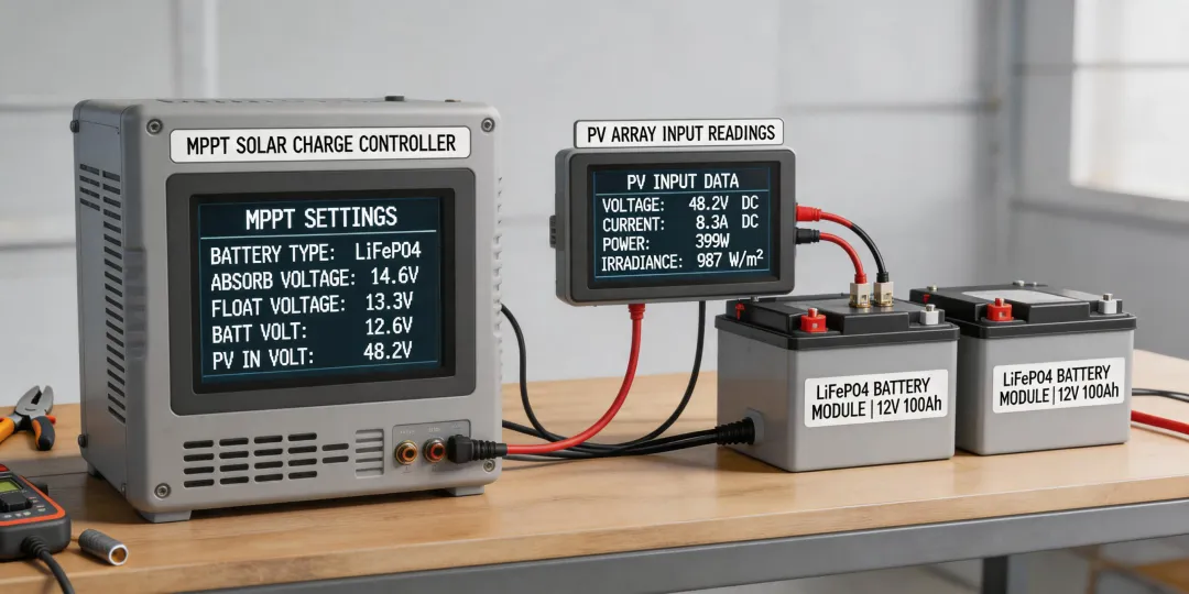
Step 1: Verify the LiFePO4 Voltage Curve (Don't Trust the Default)
This is where I screwed up. Every Epever MPPT controller comes with a default battery type—usually Sealed (SEL) or Gel. It is never set to User (USE) out of the box. If you are connecting to a LiFePO4 battery and you skip this step, you will either undercharge or overvolt the battery.
The specific action:
- Navigate to the battery type setting in the MT50 remote meter or via the Solar Station Monitor app.
- Change it from 'Sealed' to 'User'. This unlocks adjustable parameters.
- Set the Absorption Voltage to 14.4V (for a 12V system) or 28.8V (24V system).
- Set the Float Voltage to 13.8V or 27.6V respectively.
- This is non-negotiable. The default 'Sealed' profile uses a higher absorption voltage (often 14.6V or more) which is safe for lead-acid but can trigger BMS protection on a LiFePO4 pack.
I actually learned never to assume 'default settings' mean 'correct settings' after that 2019 disaster. The Epever manual lists these voltages, but nobody reads the manual until something breaks, right?
Step 2: Calculate Your Array Voltage vs. Controller Limit
Here's another mistake I see a lot. People buy an Epever 30A MPPT and think they can throw any solar panel array at it. Wrong.
Most Epever MPPT controllers (like the Tracer AN series) have a max PV input voltage of 100V (for 12V systems) or 150V (for 24V systems). But—and this is the part people forget—the cold temperature compensation factor increases the voltage of your panels.
The specific action:
- Take your panel's Voc (Open Circuit Voltage) at 25°C.
- Apply a safety factor of 1.25 for temperature variations (especially in cold climates).
- Ensure the total series string voltage (Voc x number of panels in series) multiplied by 1.25 does NOT exceed the controller's max input voltage.
- Example: If Voc is 22.5V and you put three in series (67.5V), the cold weather voltage is roughly 67.5V x 1.25 = 84.4V. If your controller max is 100V, you are safe. Add a fourth panel in series (90V x 1.25 = 112.5V) and you will fry the controller on a cold morning.
Pro tip: Always leave a 10-15% buffer. Don't push it to the limit.
Step 3: Don't Forget the Battery Communication (If Applicable)
If you are pairing an Epever inverter (like the Epever UP series) with a smart LiFePO4 battery that has a BMS communication port, you have a choice. You can either let the BMS talk to the inverter or set it manually. Most installers skip the communication cable because 'it's easier to set the voltages manually.'
Here's the thing: If you set it manually, you lose the ability for the BMS to tell the inverter to stop charging when a cell gets too cold or too hot. This isn't a huge deal in a climate-controlled garage. But in a remote cabin where temps drop to -10°C? It matters.
The specific action:
- Check if your Epever inverter and battery support a common communication protocol (like CAN bus or RS485).
- If they do, use the cable. It's an extra $15-30 in parts, but it can prevent a $400 battery replacement down the line.
- If they don't support communication, manually set the absorption and float voltages based on the battery manufacturer's specs (as in Step 1).
Step 4: Grounding and Fusing (The Overlooked Safety Check)
I once visited a site where the installer had connected a house solar system using an Epever 60A controller. The battery bank was four 100Ah LiFePO4 batteries. Looked great. Except they used a 50A fuse between the controller and the battery. The controller can output 60A. The fuse was a bottleneck that could blow under heavy load.
The specific action:
- Fuse each battery bank positive cable individually (use a Class T fuse rated for the maximum discharge current).
- Use a fuse or breaker between the controller and battery rated at 1.25x the controller's rated current. For a 30A controller, use a 40A fuse.
- Ground the system appropriately: negative battery terminal to a single ground rod using at least 6 AWG wire (or as per local code).
This isn't optional. Ungrounded systems can float at dangerous voltages. I've seen it happen.
Step 5: Test the System Under Load (Not Just at Idle)
This is the final step that gets skipped the most. You set up the controller, see the blue LCD screen glow, and think 'job done.' But the real test is when the system is actually working.
The specific action:
- Turn on a significant load—like a small fridge or a pump drawing about 300W.
- Watch the battery voltage on the Epever display. Does it sag below 12.0V under load? If so, your battery bank is undersized or the cables are too thin.
- Check the controller temperature after 30 minutes under full solar load. If it's too hot to touch (above 50°C), improve ventilation.
- Verify the LiFePO4 SOC vs Voltage relationship. A fully charged LiFePO4 cell sits at about 3.45V (13.8V for a 4-cell battery). If your controller says 13.8V and the battery is resting, that's fine. But if it says 13.8V under a heavy load, the battery is likely low on charge.
That last point is important. Many installers confuse 'resting voltage' with 'working voltage.' A LiFePO4 battery at 13.2V resting is about 20% full. Under a 200W load, it might drop to 12.8V, which looks like 0%. But if you remove the load, it bounces back up. Knowing this curve saves you from ordering an unnecessary battery replacement.
Final Thought: The Jackery vs. Epever Comparison
I get asked about this a lot. People compare a Jackery Solar Generator 1500 V2 with a full Epever-based system. They are not the same thing. The Jackery is an all-in-one portable unit. An Epever system is modular. If one component fails (like the Jackery's inverter), you replace the whole unit. With Epever, you replace just the controller or the inverter. Over a 5-year lifespan, the Epever modular setup is cheaper to maintain. But it requires more setup knowledge upfront. That's why this checklist exists.
To sum it up: check the voltage curve, size your array properly, don't skip the communication cable, ground everything, and stress-test the system. That's it. Simple. But the consequences of skipping any step are expensive. Period.